Flight mechanics is a well-covered topic in aerospace and mechanical engineering studies, but most of the literature is not targeted for a general audience. A brief overview of the parts of an airplane and the principles of flight is provided in this article to better understand flight.
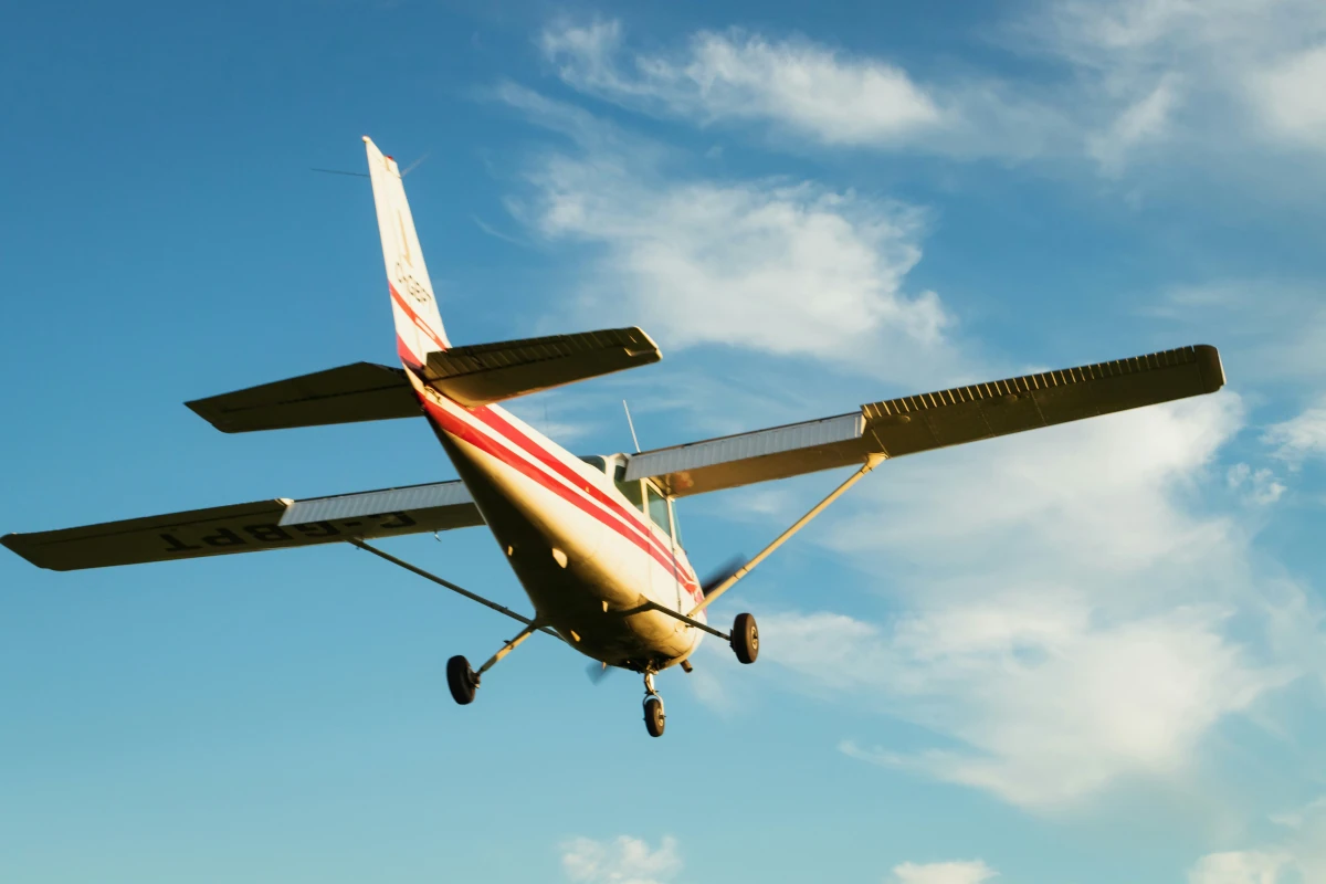
Main Parts of an Airplane
The main parts of an aircraft are wings, fuselage, and empennage/tails. There are other components, such as landing gear, control surfaces, propulsion system etc., but design choices are mainly dictated by these three components.
Wings
Wings are the most essential lift-generating elements on an aircraft. The wings should be able to lift the aircraft’s weight in different flight regimes (speed and altitude); however, the design is optimized for cruise speed. Lift generated on the wing is dependent on many design parameters, but the main contributors are the wing area and airfoil geometry.
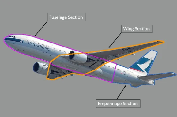
Fuselage Section
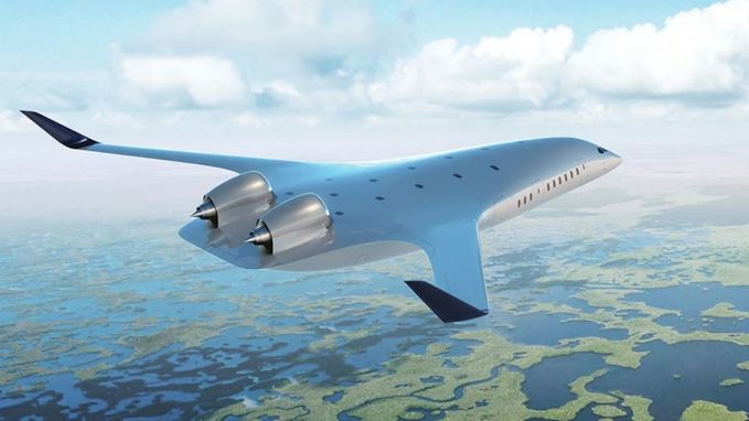
Fuselage is the usable compartment that is generally designed to have a sleeker, more aerodynamic shape. Slenderness ratio is the design parameter and is defined as the ratio of fuselage length to diameter (L/D); this ratio is selected to optimize the drag for a given usable volume. BWB configuration has eliminated the need for a separate fuselage by accommodating usable space into the wing design. This reduction in surface area or wetted area helps in reducing the skin friction drag, which has a noticeable impact at slow speeds but a significant contribution at high- speeds.
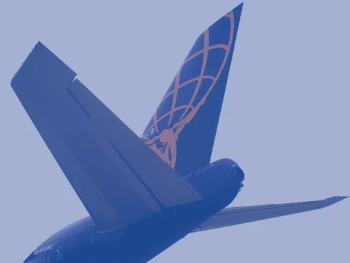
Empennage Section
A typical rear mounting configuration of horizontal and vertical stabilizers is called the empennage section. Stabilizers or tails, are placed at the aft section of the fuselage to maximize the moment arm, so that tail size would be minimized while generating the same effectiveness.
Horizontal Stabilizer
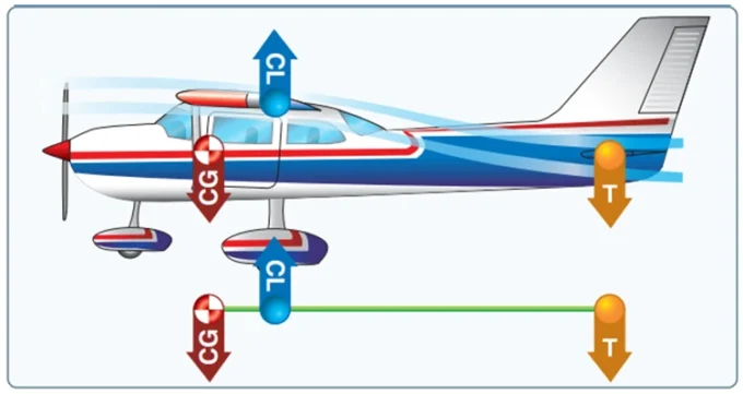
Practical aircraft design considerations require aircraft to be flightworthy throughout the center of gravity range. Aircraft are required to have a minimum surface area to reduce drag, such as in a flying wing or blended wing body (BWB) with no additional surface. However, practical variation of the center of gravity (CG) due to the distribution of passengers, luggage, fuel variation, and other payload configurations requires a properly-sized horizontal stabilizer to ensure proper stability and control. This typical configuration generates negative lift (putting a dent on the lift of the wing), as shown in the figure below:
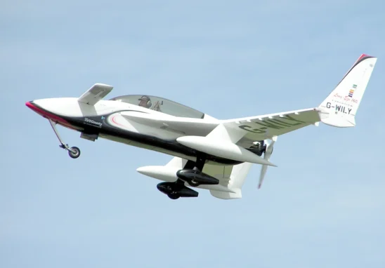
Another arrangement is a canard configuration, in which the tail is placed forward of the CG. In this arrangement, the tail is now lifting, thus increasing efficiency. However, a wide CG range may be difficult to manage in this configuration, and a restricted wing span (to manage aspect ratio) may be required to ensure static stability in all phases of flight. Therefore, canard configuration may not be an ideal choice to meet all design goals. But it is worth mentioning that for single-point design performance, this configuration has proven to be more fuel-efficient in terms of range.
Vertical Stabilizer
A vertical tail is used to provide “Weather Cock” stability to an airplane so that it will not “side-slip.”. The effect of side-slip is bad in two ways: first, the wing is designed for longitudinal flow and does not perform well under side/lateral flow; second, side-flow generates loads that can alter the flight path of aircraft in an undesirable way. Side-slip can also cause passenger discomfort on commercial flights.
Flight Envelope
The flight envelope defines the boundaries of an aircraft’s flyable speed and altitude. A flight envelope typically has a box shape with four corner points, defining a slow speed limit, a high speed limit, a maximum altitude and a sea level performance line. The flight envelope is a function of the aircraft design as well as the selected propulsion system. In general, speed lines are related to aircraft design and maximum altitude is dependent on propulsion.
Relative Flow Angles
Relative flow angles are important in the generation of forces on the aircraft. The two angles are the angle of attack (AOA) and the angle of side-slip (Beta). A detailed description of aerodynamic forces can be found here. Angle of attack is the longitudinal flow angle between the relative wind direction and airfoil cord-line and is the most sensitive parameter for generation of the lift

The angle of side-slip is the side-wise or lateral component of the flow. Side-slip is mostly an undesirable effect and therefore is minimized using the rudder control surface.
Flight Mechanics
Aircraft Orientations and Axes
A flying aircraft has six-degrees of freedom (6DoF) motion; therefore, it can move in three planes and rotate across three axes, which are pitch, roll and yaw. Angles are measured relative to the ground plane, also called the local geographic reference frame, where pitch rotation happens in the longitudinal plane and causes nose-up and nose-down movement of the aircraft. Roll axis rotation, the roll angle is measured in the lateral plane and wings move up and down relative to the ground. Finally, yaw is the out-of-plan lateral movement of the aircraft nose.

It is worth mentioning that aircraft orientations are relative to the ground and flow angles are relative to the incoming wind. For example, for a wing-level flight, the yaw angle and the angle of side-slip are measured in the yaw plane, but both are not same as the side-slip can occur without a yaw angle and vice versa. Similarly, the pitch angle and AOA are relatable in some cases but are essentially different parameters.
The Four Forces on Aircraft
The four principle forces of flight are lift, drag, thrust, and inertia/weight. Lift is produced to balance the inertial effect of weight (it will be more than 1G for maneuvering aircraft !) and thrust are set to match the drag at the desired flying speed. Ideally, we want to minimize the drag while maintaining lift. Since drag is also a function of the lift being produced, a better measure of aerodynamic efficiency is the ratio of lift to drag (L/D). A designer tries to maximize this ratio in the flight envelope.

Steady or Trim Flight Condition
A steady-state or trim condition, is the state of an aircraft when the sum of all forces and moments is balanced so that its accelerations (linear and angular) are zero. An airplane has to fly at a certain AOA to maintain the lift while maintaining its flight path; additionally, for a steady-level condition, aircraft have a zero flight path angle. This will be in contrast to a steady climb condition in which aircraft maintain a non-zero flight path angle while maintaining the same amount of lift.
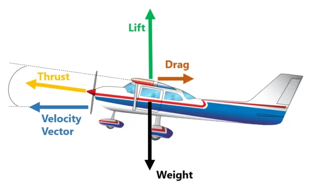
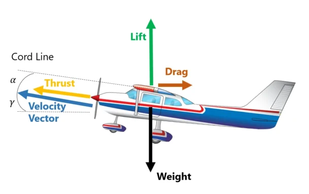
The energy required for flight is essentially supplied by the propulsion system to overcome the drag. Any “Excess Power” set by the pilot will either cause a speed rise or can be used to increase the altitude. Therefore, if the same airspeed is maintained by the pilot while in trim state, the rate of climb (vertical speed) gain is proportional to the excess power.
