What is an Airfoil
The airfoil is the cross-section of the wing that is facing the incoming airflow. This section is specifically designed to provide the lift at a wider range of lift coefficients and values of angle of attack (AOA). One of the important characteristics of this curvy, thick cross-section is that it can delay flow separation and maintain attached flow in front of an adverse pressure gradient.
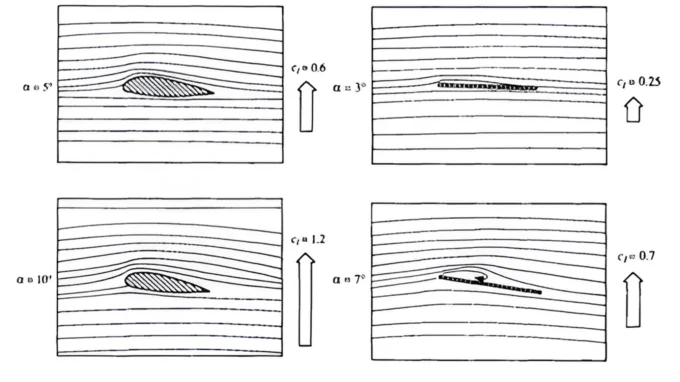
One can appreciate the airfoil section by comparing it with a flat plate model. Both of these section of same length will provide similar lift up to small AOA (smaller lift coefficients). But as the AOA is increased, flow separation starts at the leading edge of the flat plate; on the other hand, on airfoil surface flow separation is delayed . In fact, the flow separation of properly designed airfoil starts at the trailing edge, which is a desirable phenomenon.
Understating Flow over Airfoil
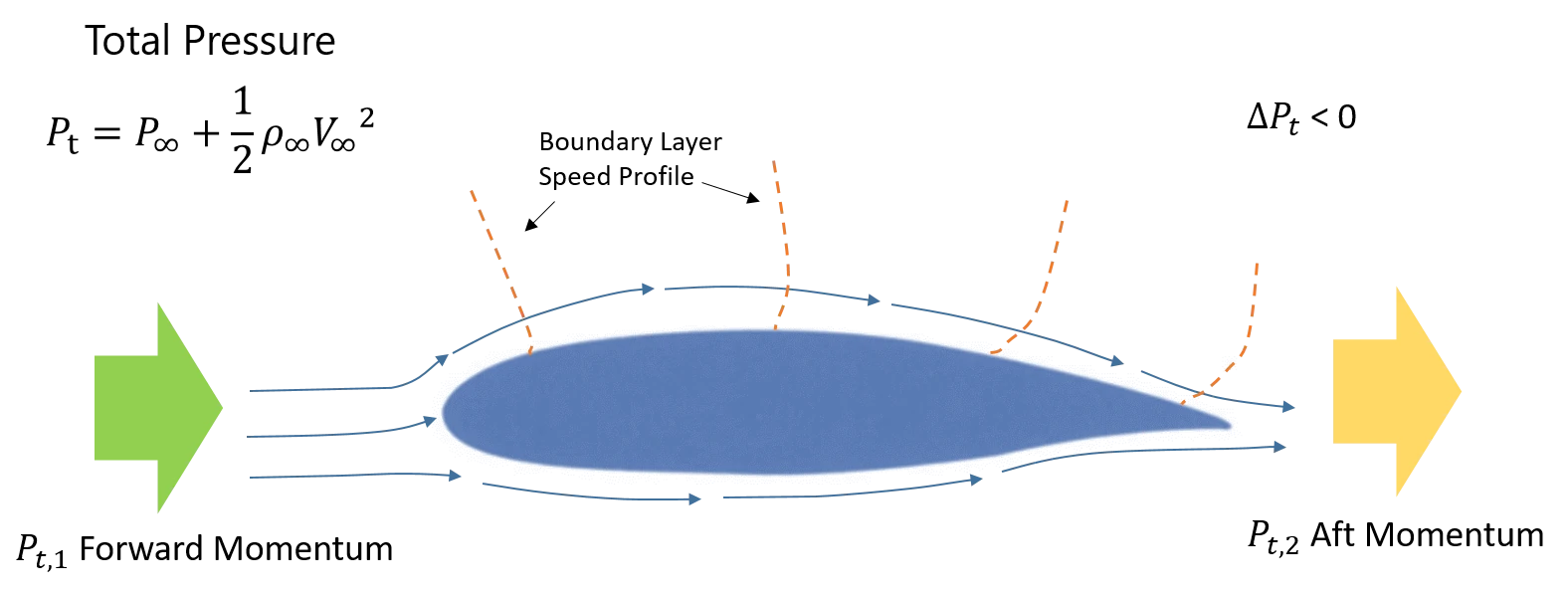
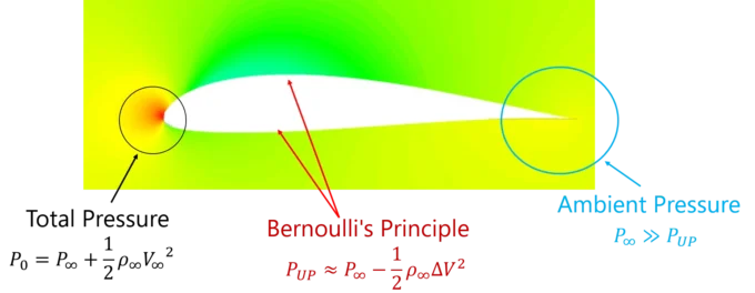
There are many theories that can explain the lift generation over a wing/airfoil. Mostly, it is attributed to Bernoulli’s principle, which states that the speeding up of flow on upper surface causes a pressure drop as compared to lower surface; thus, an imbalance of pressure generates lift. The above statement is true to some extent; in fact, Bernoulli’s principle is a form of law of conservation of momentum or kinetic energy. But the real reason for flow speedup on the upper surface is the starting vortex at the trailing edge of the airfoil.
Starting Vortex on Aero Foil
Imagine that at the start of airflow, two streamlines of flow depart at the leading edge; one follows the lower surface, or shorter route, and the other follows the upper surface, or longer route. By the time lower flow reaches trailing edge, it tries to curl around the trailing edge to fill the void created by the absence of upper flow. Instead of turning around the trailing edge, generate a starting vortex. This starting vortex forces a suction condition over the upper surface; a rapid drop in the pressure causes the upper flow to speed up and match the lower flow, thus achieving equilibrium.

The pressure distribution on upper surface is of great interest in airfoil design. Usually, suction peaks occur near the leading edge up to the maximum thickness point. The pressure starts to increase gradually as the flow marches along the surface until it reaches the trailing edge.
Aerodynamic Coefficients of An Aerofoil
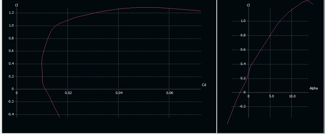
Aerodynamic lift and drag forces generated over the surface of the airfoil are plotted as lift curve and drag polar, respectively. For an airfoil, lift at zero AOA is a design characteristic; as AOA increases, lift coefficient CL increases linearly at a gradient of approximately 2*PI per radian. Near a stalling angle, the lift curve starts bending until full flow breakdown occurs at stall AOA. Drag polar is generally plotted with lift coefficient on one axis and drag coefficient on other axis. This graph represents the aerodynamic efficiency of a shape.
Typical airfoil aero-charts has moment curve as well, which is measured at quarter (25%C) of the airfoil section cord or cord length. The moment coefficient is also a measure of the distance between the center of pressure and the quarter cord point.
Airfoil Design Parameters
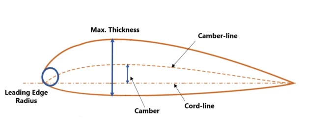
- Cord-line
- Camber and camber-line
- Maximum thickness
- Location of camber and max. thickness
- Leading edge radius
Airfoil cord line is a line joining the leading edge to the trailing edge of the airfoil. It is basically a local reference for the airfoil, as all other design parameters are defined in terms of cord length.
Camber and Camber Line
A camber line is a line that is obtained when slicing the airfoil thickness in half. Camber defines a degree of incident to the incoming air; therefore, more camber means more incident and a positive lift coefficient even at zero AOA. An amount of camber is defined as the maximum distance between the camber line and the cord line at any point as a percentage of cord length; a typical value of 2% to 6% can be found on airfoil sections. Moreover, an amount of camber slightly improves lift curve slope as well.
An airfoil with zero camber is essentially a symmetrical cross section. Thus, symmetrical airfoil has no lift at zero AOA and has major applications in high-speed aircraft and empennage/tail design.
Maximum Thickness
Thickness distribution on airfoil gives it aerodynamic shape and helps improve the flow separation characteristics. A maximum thickness ratio (t/c) of airfoil (also defined in terms of the percentage of the cord) has a value range of 8% to 18% for typical airfoils. T/C has direct proportionality with maximum lift coefficient or CLmax as shown in figure below:
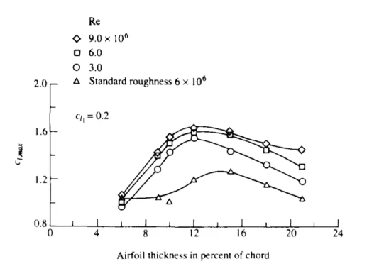
Max. t/C also has direct effect on stalling characteristics of the airfoil, an ultra-low thickness airfoil will act as a flat plate and will have separation bubble ahead of 50% of cord. This will give poor stalling behavior as compared to moderate or high thickness airfoil (13% ~ 18%).
Maximum Thickness and Camber Location
The location of the maximum thickness can alter the pressure distribution, stalling characteristics, and CLmax capability of an airfoil. A near-leading edge distribution can raise the suction peak and give a higher value for CLmax. But the downside of it would be a relatively abrupt pressure gradient that may lead to poor stall behavior. On the other hand, an aft-ward location of the t/C (30% to 40%) will give a lower CLmax but relatively gentle stall behavior.
Location of t/C and max. camber point also has direct implications on the aerodynamic center (the center of forces), and an aft-ward configuration may give high pitch-down moment at quarter of cord C25%.
The location of max. camber is somewhat related to t/C location due to shape consideration; but exceptions do exist. For example, in flying wing configurations, a reflex airfoil is used where the maximum camber point is well away near the trailing edge (TE); in fact, camber is negative to generate a desirable pitch up (positive) moment. Similarly, laminar flow and transonic airfoils have their camber locations near TE.
Leading Edge Radius
The leading edge (LE) radius has a direct effect on the stalling behavior and CLmax of an airfoil. A higher LE radius reduces the suction peak on the top of the airfoil, thus generating stable flow (delayed stall) but a slightly lower CLmax.
Another important aspect of LE radius is its impact on ice accumulation on wing. Ice formation is a critical hazard for wings, as it can drastically reduce their performance. In contrast to intuitive thought, a higher value of leading edge reduces the chances of icing. The reason for that is that a rounded LE has more impact on the velocity profile of streamlines around it, hence deflecting most of the water away from it as compared to a sharp leading edge.
Airfoil Selection Guideline
Airfoil selection is an art to better trade-off the design choices based on application, manufacturing, off-design, and performance considerations. In applications that require a single point design (i.e., a fixed-speed drone), optimizing single-point performance is sufficient. But for aircraft that have to be flown at various flying speeds, optimizing cruise performance, restricting take-off and landing speeds, and improving maximum speed are objectives that are total in contrast and can make design choice difficult. Therefore, it is important to identify the key performance indicators (KPI) to make a rational decision by weighting out various candidates.
An example of KPI for airfoil selection is given below:
- Flight Regime (Single Point or Envelope)
- Identify the flying Mach and Reynolds Number
- Select Intended flow behavior (Laminar or Turbulent)
- Identify required design lift coefficient
- Identify required maximum lift coefficient
- Flow Separation and stall behavior
- Ease of manufacturing (machining, hand-built mold)
Discussion on different airfoil series is intentionally avoided to better explain the design concepts, and valuable resources such as UIUC are already available.
List of Airfoils by Application
| Airfoil Name | Application |
| NACA 2412 | Cessna C-172 |
| NACA 64A318 | C-130 Hercules |
| NACA 43018 (Modified) | ATR-72 |
| NACA 64A204 | F-16 Fighting Falcon |

1 comment
[…] only and understanding the airfoil design is a separate subject and has been covered here A Detailed Guide to Airfoil Geometry It is important to discuss the induced drag as it one of the key performance parameter for a 3D […]
Comments are closed.